GM 2D-XRD facility offers a state-of-the-art 2D X-ray diffraction system for advanced characterization of materials:
- Vantec 500 Detector, 2048 x 2048 resolution
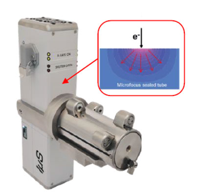
- Microfocus X-ray source, for very high x-ray intensity while utilizing only 50 W of generator power
- Goebel mirror optics for parallel incident x-ray beam, pinhole collimator 0.3, 0.5 and 0.7 mm spot size
- 5 axis goniometer: fully automated, for 2Theta, omega, phi, chi scans, and x, y, z translation stage.
- Large mounting surface, together with xyz stage enables automated unattended measurement of multiple samples
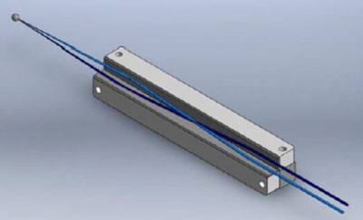
- Knife edge for reduction of air scatter and improvement of signal/noise
Features
- The facility offers unprecedented speed and data quality for 2D-XRD.
- Typical 2D sections of large fractions of reciprocal space can be done in a matter of minutes.
- Complete 3D mapping of reciprocal space can be done in a matter of an hour.
- Custom developed software by the PI enables reconstruction of the entire 3D volume of reciprical space.
- Arbitrary sections of the reciprocal collected space can be visualized and features of interest quantified
- Arbitrary number of pole figures can be rapidly reconstructed from the 3D volume.
PIs campus-wide are welcome to use the facility.
Training for students who have passed the Radiation Safety Training is provided.
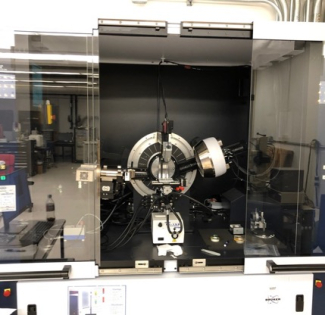
Platform Description - Bruker D8 Discover
Advanced X-ray Diffraction System for Material Research Applications
The D8 DISCOVER with DAVINCI design increases ease-of-use with real-time component detection, plug-and-play functionality and fully integrated 2-dimensional XRD2 capabilities. These unique features allow the user to easily switch between all materials research X-ray diffraction applications, including reflectometry, high-resolution diffraction, grazing incidence diffraction (IP-GID), small angle X-ray scattering (SAXS), as well as residual stress and texture investigations.
An integral part of the D8 DISCOVER with DAVINCI design is the new DIFFRAC.SUITE™ software with consistently implemented automation functionality. An X-ray optics module, a detector, or any accessory mounted onto the instrument registers itself in real-time with its relevant parameters and analytical capabilities, including powerful detection of possible component conflicts. The factory aligned, snap-lock X-ray optics provide true ‘plug-and-play’ functionality, including automatic and tool-free switching of the diffraction geometry with minimal user intervention. The DIFFRAC.SUITE offers intuitive operation based on a graphical user interface that can be customized to match the operator’s requirements.
Location
University of Houston
Cullen College of Engineering
Engineering Building 1, Room N163
4226 Martin Luther King Boulevard
Houston TX 77204-4006
System Configuration
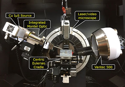
XRD Source and Optics
IμS Microfocus Source
- Small Focus (0.05 mm Ø)
- 50 W (50kV/ 1 mA) → 20kW/mm ²
- Air Cooled
- > 7 year Tube life
- ~3% Loss per Year
- 3 year Warranty
Integrated Montel Optic
- Double multilayer mirrors
- Divergence: < 0.05 ° in both directions
- Intensity: > 1 x 10⁸ CPS
- Beam Size: 1 x 1 mm
Multipurpose Stage
- XRD, GIXRD, IP-GIXRD, SAXS, GISAXS, residual stress, texture, HRXRD
- Optional accessories for extended capabilities:
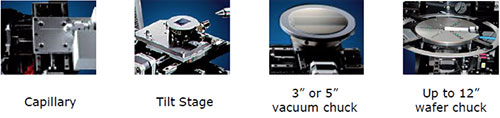
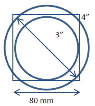
Mapping Capabilities
- Full wafer mapping up to 3"
- Full diagonal wafer mapping up to 4"
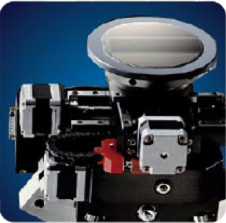
Centric Eulerian Cradle
- One stage fits all applications
- Wide Mapping capabilities
Goniometer, Detector and Sample Size Specifications
|
Drives |
|
|---|---|
|
Chi-Range |
-11° to 98° |
|
Phi-Range |
Unlimited |
|
X-Range |
±40 mm |
|
Y-Range |
±40 mm |
|
Z-Range |
2 mm |
|
Sample Weight & Size |
|
|---|---|
|
Max Weight |
1000g |
|
Max Size |
12" diameter 40 mm height |
|
VÅNTEC 500 |
|
|---|---|
|
Modes |
2D |
|
Size |
140 mm diameter |
|
Pixels |
2048 x 2048 |
|
Pixel Size |
68 μm |
|
PSF |
200 μm (~3px) |
Application Examples
Rapid 2D Mapping of Reciprocal Space
Rapid characterization of samples can be obtained by selected scans of planes of interest, typically in rocking curve or phi axis rotation scans. These scans are accomplished in a matter of minutes due to the intensity of the source and high signal to noise ratio of the detector. Multiple frames can be combined, including frames acquired at different Chi angles, via custom developed software by the PI.
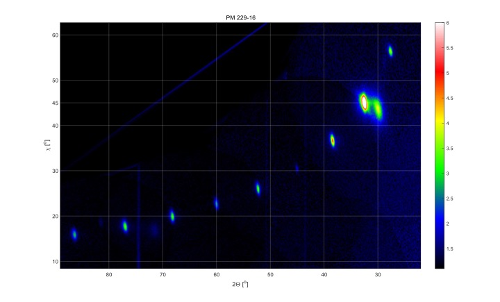
2D Map of REBCO superconductor containing 00L and 10L peaks. The entire reciprocal space shown here can be measured in a matter of several to 30 minutes, depending on the desired signal/noise and sample peak intensity:
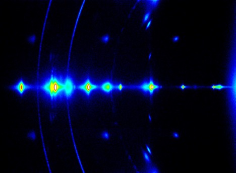
Application example: REBCO superconductor, scanned over 8 frames, covering 00L and 10L peaks from 001-00(10) and 101-10(10). Maximum 2Theta covered in this example is over 90 degrees. The entire map was obtained in less than 30 minutes. Intensity is shown on log scale:
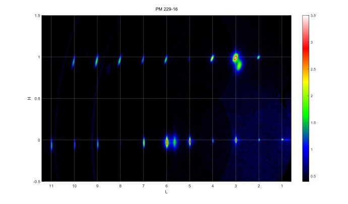
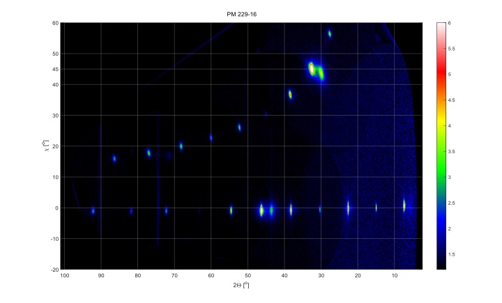
Eight frames, shown in 2Theta-Chi coordinates, intensity shown on log scale. Peak angles and constant 2Theta values can directly be read from the plot:
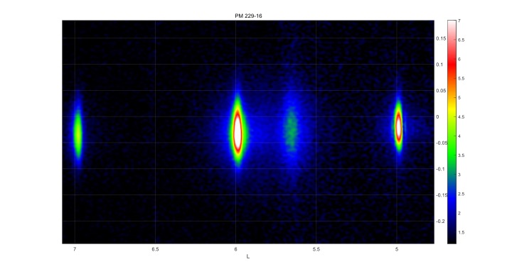
Magnified details of 10L peaks in 2Theta vs Chi coordinates:
Magnified detail of 005-007 peaks:
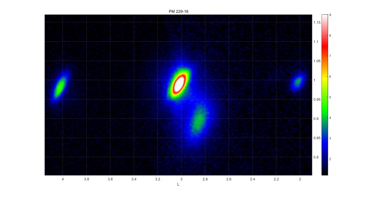
Magnified details of REBCO 102, 103 and 104 peaks and epitaxially grown 101 BaZrO3 nanorods:
Fast 3D Mapping of Reciprocal Space
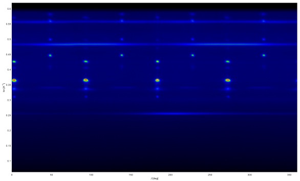
A 3D data volume of reciprocal space can be collected in a matter of 1-2 hours due to high source intensity and high detector signal to noise ratio. Several examples of various projections of the 3D data volume are provided below, where the entire reciprical space of interest is mapped as a 3D volume. If needed, e.g., for low symmetry systems, multiple 3D scans can be obtained and merged into a single 3D data volume. The data can be readily processed in terms of reciprocal space vector units, angles, multiple pole figures or orientation distribution function.
Azimuthal angle (x axis) vs q-norm (y –axi) for a 360 degree 3D scan of a superconductor sample. The original data are a 3D reciprocal space cube:
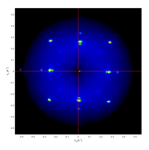
Qx-Qy projection of a 3D reciprocal space cube collected in 1 hour:
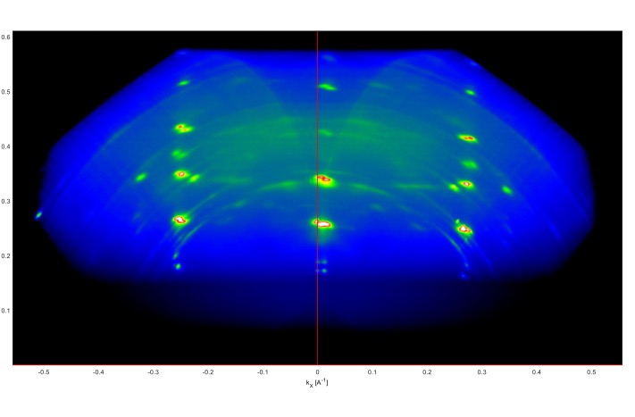
Qx-Qz projection of a 3D reciprocal space cube collected in 1 hour.
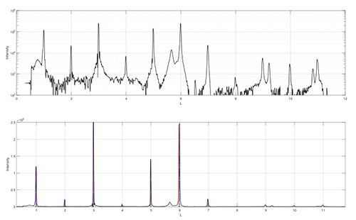
Integration of 2D and 3D scans into 1D data and post-processing
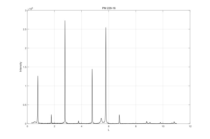
The acquired 2D and/or 3D maps can be readily processed to obtain 1D plots of interest, such as peak intensity vs 2Theta or Chi angles, together with noise removal, full Voigt-profile fitting, quantification of peaks (asymmetry, multiple peak fitting for overlapping peaks, etc.), lattice parameter estimation using Nelson-Riley analysis, strain and domain size analysis and identification of unknown phases. Most of the listed post processing is automated by a custom developed software by the PI and can be done on request. A software provided by Bruker, EVA, is also available on site for fast post-processing of data directly by the user.
High quality 1D integration data from 2D (3D) scans for quantification of peaks:
Some of examples that the 3D scans on this system have been and can be used for:
Nelson-Riley lattice parameter estimates
Peak analysis using full Voigt profile fitting
In plane and out of plane texture quality
Stacking fault analysis via 00L peak streaking and peak position deviation
Strain analysis
Detection and identification of multiple phases
Orientation distribution function
Most of the listed features are automated via custom developed code and/or software provided with the system.
High quality 1D integrated data for rapid quantification of data: